
Finite Element Analysis relies heavily on the creation of a proper mesh system to begin the analysis of the effects of boundary conditions and applied loads on a model. Abaqus has many tools available for the creation of a mesh. With the variety of options and important steps necessary to create a proper mesh it is quintessential to understand what each tool accomplishes within the software.
A meshing is a geometrical approach to approximating a physical portion of a model. These geometrical approximations are created based on the nodes that can be found throughout a part assembly. Meshing once post-processed, also allows the user of Abaqus to understand the areas that most likely produce failure given the material properties established in the preceding steps. [1]
The importance of meshing can be seen throughout our daily lives. When a design element is analyzed with a great mesh system certain physical property can then be approximated. Whether it be the maximum load a vehicle’s suspension system can handle, the allowable internal pressure on a pipeline, the maximum weight capacity of a chair, to even things like the amount of allowable pressure on a pencil lead piece before it snaps. A proper mesh will allow the user to better understand the limitations of their design and that is why it is important to take a deeper look into the creation of a mesh system.
Figure 1: Pipe Meshing
 Mesh Convergence
The generation of mesh can be a time-consuming part of the FEA analysis. This is due to the level of accuracy of the solution which relies heavily on the quality of the mesh generated. So, an important question to ask is how do we know if a mesh is accurate enough for the given geometry?
With the many different tools available for the creation of a mesh in general it is that the smaller sized cells will generally result in more accurate results. The downside to the creation of smaller sized cells is that there is a tradeoff between accuracy and computational time. As the size of the mesh cells decrease the computational time increases exponentially causing certain simulations to take longer per run. It is important to understand which portions of your geometry will require finer mesh and which can go without the finer mesh to retain an acceptable level of accuracy and save on computational time.
Mesh Sizing
The size and quantity of a mesh can be modified with the creation of more seeds. The greater the number of seeds along an edge will lead to the establishment of a more densely packed mesh system. Even the approximate size of the mesh can also be altered when using both seed creation options. In order to establish a general seed of uniform size the best tool for use would be the Seed Part. This will allow for the creation of a mesh system with uniform shapes across the entire part. On the other hand, if there are any edges or corners that require a finer set of mesh geometry then Abaqus has a function where the user can use Seed Edge tool and create an alternative size/shape for the seeded part.
To properly create a mesh, it is essential to use a combination of these two tools. This will help with the establishment of a more accurate mesh, whose importance was discussed earlier. For instance, the areas in which loads are applied to our generated parts will require the use of the bias option under the seed edge tool to create a portion of the edge with more seed elements. The use of these tools will then lead to the verification of the mesh which will allow Abaqus to analyze the created mesh for any areas where unusable mesh may exist and what areas may need a correction.
Figure 2: Pipe Seeding
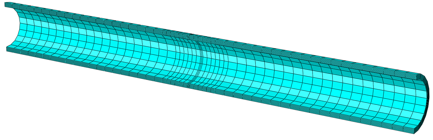
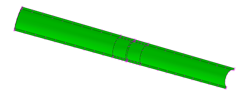 Figure 3: Resulting Meshed Pipe
 Conclusion
The creation of mesh is a vital part of Finite Element Analysis provided by the Abaqus software. Each element of the mesh is vital to ensure that there is an accurate reading of the response to any external contact, load, boundary condition, or any other stimulate whether it be mechanical or thermal. With the vast variety of different properties of the mesh that can be altered the user has major control over the flexibility of their results during the job visualization portion.
If you want to have a better understanding on how to apply a mesh for your product, please do not hesitate to contact us.
Contributors:
Georgiy Makedonov, M.S., is an FEA Engineer at VIAS3D. has over 4 years of industrial experience in finite element analysis simulation, technical support, and consulting. His professional interest involves designing, developing, and evaluation of rigid pipeline systems, teaching, and FEA analysis using SIMULIA Abaqus. He holds Master of Science in Mechanical and Subsea Engineering from University of Houston.
Ahad Muhammad, B.S., is an FEA Engineering Intern at VIAS3D. has recently completed his Finite Element Analysis course while also working as a consultant in his past jobs. His professional interests lie in the development, design, optimization and evaluation of new technologies and mechanical features. He is going into his senior year with experience in CAD software, FEA softwares such as ABAQUS and COMSOL, and coding experience with MatLab and Python. He will graduate Spring 2022 with a Bachelor of Science in Mechanical Engineering and a minor in Mathematics from the University of Houston.
References:
[1] Dassault Systems, 2016-2019, “The Mesh Module.” 17, from http://130.149.89.49:2080/v6.14/books/usi/default.htm


